FX-controller programming - Alarms#
Getting started part 4: FX-Points - Alarms#
Introduction#
FX alarm points can be virtual points or physical points.
Virtual alarm points can either be triggered by meeting criteria specified in the FX-point layer programming (e.g. if TE > 20°), or from the IEC program (a more complex combination of conditions is met).
Physical points are basically digital indications that get activated either when closed or opened (programmable in the FX-point layer).
In the FX-point layer programming you can additionally add on and/or off delays. This means that for the example where the alarm point is trigger when TE > 20°, and the on delay is 10 seconds, the alarm will only be activated when TE has been > 20° for more than 10 seconds consecutively. The off delay works in a similar way.
Alarm point LockState#
Alarm points can have more values for the LockState than other points (See the “FX-points layer” section in part 1 “Logical setup” of the FX-controller programming basics lesson).
This is to indicate whether an alarm has been acknowledged or not.
This way, even if an alarm is no longer active, you can still see that the alarm has been active, and possibly take the necessary non-urgent actions. Some other processes might require on-site intervention, and so these processes can be programmed to stop until all linked alarms have been acknowledged.
The LockState for an unacknowledged alarm is the same as the normal LockState (so, 0, 1 or 2) plus ten, so 10, 11 or 12. You can get the point’s LockState with GetLockSateF function in OpenPCS, and subsequently apply a DIV or MOD operation on it to get the “normal” LockState value or to get the acknowledgement status.
NOTE: the graphic symbols for an alarm point reflect the value AND the acknowledgement status. This means you need symbols for values 0, 1, 10 and 11 for all alarm elements in your graphics (even though the actual value of the alarm point can only be 0 or 1).
Alarm groups and alarm devices#
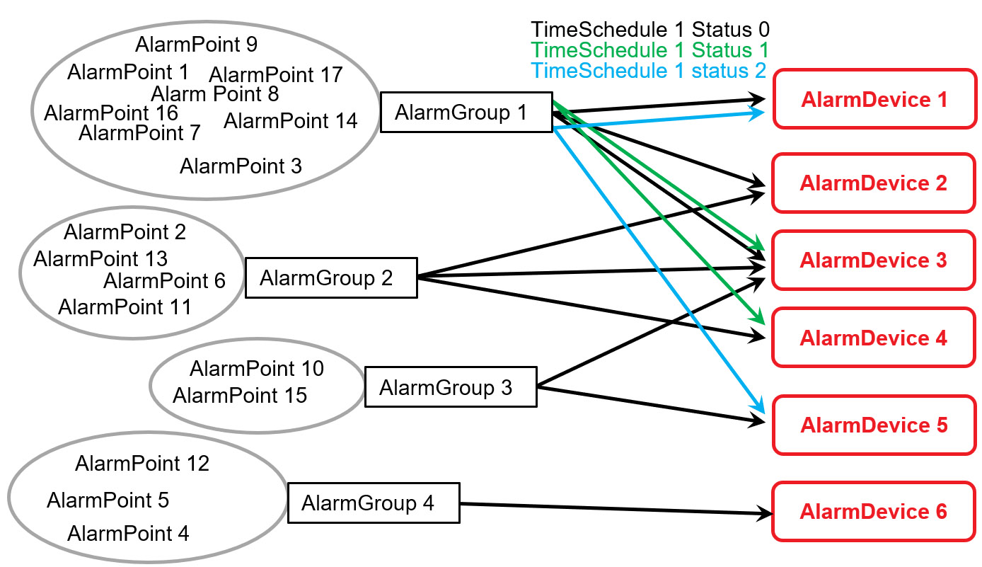
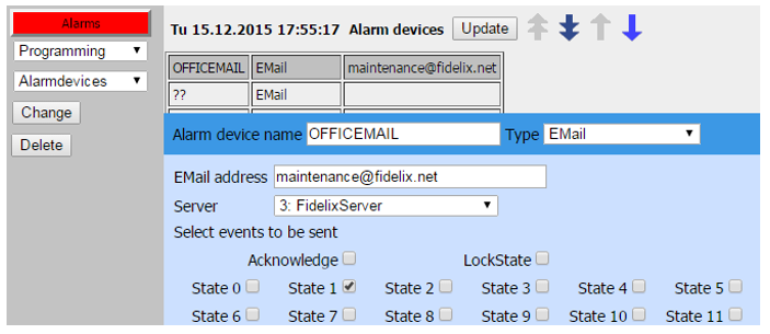
Alarm points on the FX-controller are organised in groups. Each group can be attributed 1 or more AlarmDevices.
An AlarmDevice is a virtual device that sends out alarms to a predefined destination (email, SMS, a DO-point, a printer, …). It is also the settings of this alarm device that specify for what status of the AlarmPoint to forward the alarm to its destination (active, inactive, acknowledged, …).
One AlarmDevice can be used by many alarm groups and thus by many alarms, but each alarm can only belong to one AlarmGroup.
In addition to this, different sets of AlarmDevices can be selected for each AlarmGroup, based on the status of a TimeSchedule you can link to the AlarmGroup.
All alarm points and their behaviour are saved in the alarm log, which you can access easily by pressing the “Alarms” button on the top left corner of each screen on the user interface of the FX.
Here you can view a list of all active or unacknowledged alarms, as well as view the log of all alarm point changes and the logs of emails and SMS-messages. During setup, this log is very useful for debugging the email settings, for example.
Sending emails for alarms#
To set up sending emails for alarms, a few things have to be parametrised; 1) All details of the sending server (SMTP server) need to be entered correctly. 2) At least one Alarm Device has to be set up using the aforementioned server. 3) At least one Alarm Group has to be defined, using the Alarm Device configured above. 4) At least one alarm has to be part of the abovementioned Alarm Group.
The email server settings have to be done on the user interface of the FX. The easiest way to explain how to set up an FX to send out alarms by email is with an example:
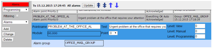
PointID: PROBLEM_AT_THE_OFFICE_AL Part of Alarm Group: OFFICE_MAIL_GROUP Selected Alarm Device (for that Alarm Group): OFFICEMAIL Selected alarm type (for that Alarm Device): EMail Selected email address (for that Alarm Device): maintenance@fidelix.net Selected server (for that Alarm Device): FidelixServer
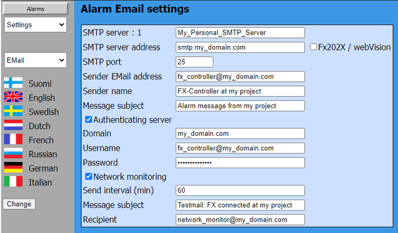
Alarm Device “OFFICEMAIL” is of type “email” and uses the parameters of “FidelixServer” to send emails. The parameters of the “FidelixServer” SMTP server are as follows for a non-authenticating server :
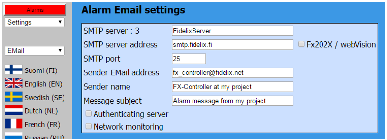
“FidelixServer” is the internal name used to identify the SMTP server settings, and maintenance@fidelix.net is the address the FX-controller will send emails to if any alarm of the “OFFICE_MAIL_GROUP” (thus, including the “PROBLEM_AT_THE_OFFICE_AL” alarm point) gets triggered.
Enabling “Network monitoring” will make the FX send out test emails at the specified interval.
You can parametrise up to 5 different “servers” here. This can also just be different sending email addresses, or different subject lines to direct the exact right message to the right recipient.

NOTE: Do not forget to click the CHANGE button after entering all parameters to save them.
NOTE: The FX does not support encryption. Most ISPs require SSL/TLS encryption on ports 465 or 587, making port 25 often the only viable option.
Alarm Group “OFFICE_MAIL_GROUP” uses Alarm Device “OFFICEMAIL” :
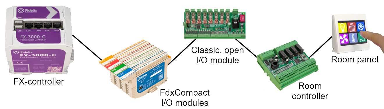
We can extend this by connecting Modbus TCP or UDP devices, or by adding more serial ports with the help of a multiLINK protocol converter. We can extend this by interconnecting several FX-controllers; they can share points, alarm devices (email sending, SMS messages, …), they can share one public IP address, … We can extend this by adding a supervisory layer through our webVision software.
You get the picture; any Fidelix system is built up of the same components. We strive for simplicity, and having a product portfolio as small as possible is our way to achieve it.
In this manual, we will teach you reach the full potential of the FX-controller; after all, the FX is a powerful controller. You might not need to add anything else to get your projects up and running.
Setting up your FX#
Changing the user interface language#
Should your controller be delivered in a language you are not familiar with, these are the steps you should take to change its user interface language:
Either on the touch screen or in your browser, log in with following credentials:
user: system
password: 24680
Once you are logged in:
On the touchscreen, where the menu is hidden by default, as to provide as much space as possible for the graphics on the pages, go to the top left corner and click or make a sliding movement inside the menu area on the left to open the menu.
In your browser; simply click in the left “menu” area to open the same menu.
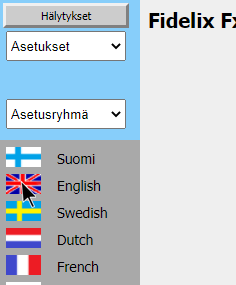
Now open the upper menu and select the THIRD item in the drop-down list to select “Settings” (in Finnish for instance, this is “Asetukset”).

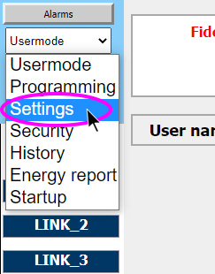
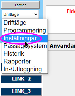
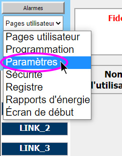
Open the lower menu and select the THIRD item in the drop-down list to select “Settings” (in Finnish for instance, this is “Asetukset”). You will immediately see flags inside the menu area with which you can choose a user interface language you are more comfortable with.
NOTE: when changing from or to Russian, the FX will reboot to start up with a different character set.
Connecting modules#
To be able to communicate, the FX needs to know the specifics of the port.
Port 1 is used to connect an SMS modem for sending out alarm messages via RS232.
Port 2 (also called Port 0) is used for M-Bus communication through the physical interface of a multiLINK module.
Ports 3-5 are the on-board serial ports (not all ports are always present on each controller!), and
ports 6-10 are ports connected through Ethernet. This can be serial ports using a multiLINK module, or genuine TCP or UDP ports.
Navigate to ‘Settings - Ports’ to parametrise the ports. Here, you can set baud rate, parity and other significant parameters for the communication with modules or other devices.
On-board RS485-ports can be used for Modbus or BACnet MS/TP communication.
Remote RS485-ports via multiLINKs can only be used for Modbus communication.
Once you have connected your I/O modules to one of three on-board serial ports, activated that port, and parametrisized it with 8 data bits, no parity and 1 stop bit, you can simply go to ‘Programming - Modules’ and click the “Find Modules” button at the bottom of the screen. The FX will poll all addresses (from 1 to 63) on all activated on-board serial RS 485 ports (ports 3, 4 and 5) to see if any module is connected. Once the FX is ready, you will see all your modules appear listed here, with the module’s firmware version and the possible % of communication packages dropped or lost.
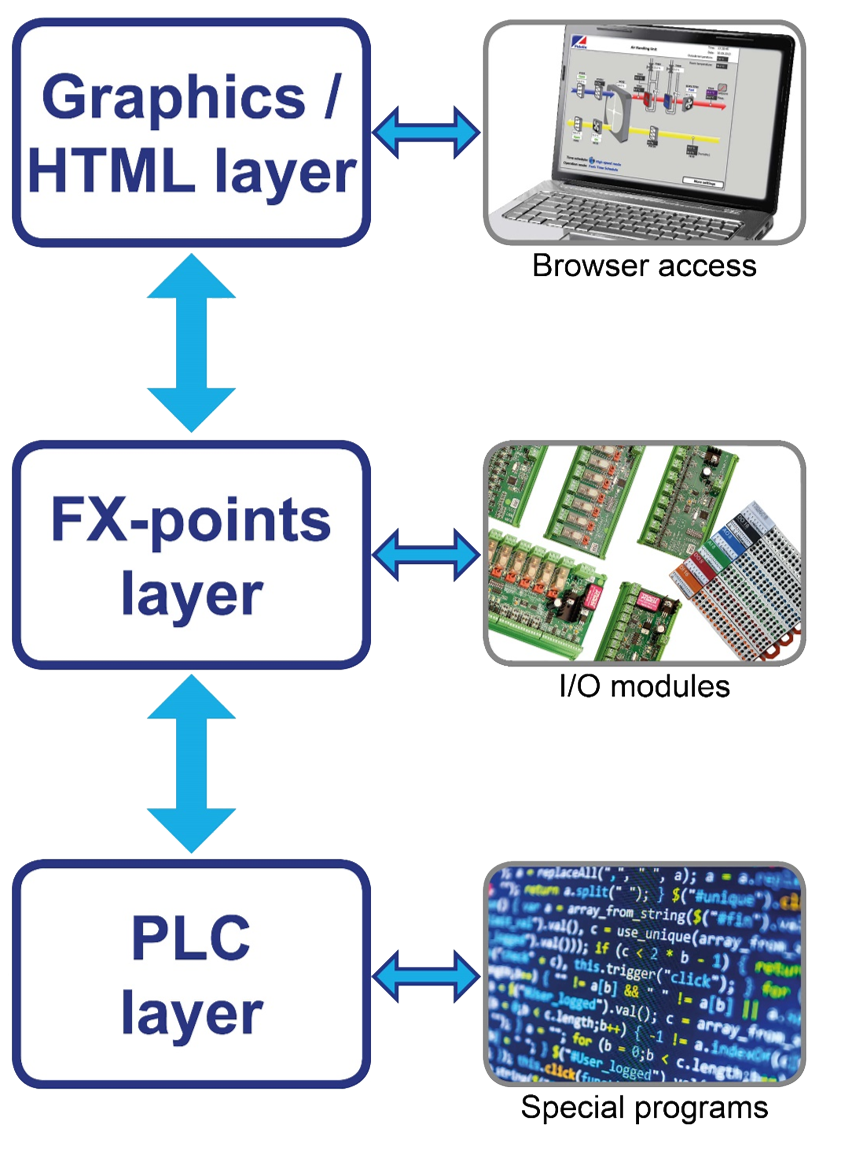
Fidelix programming layers#
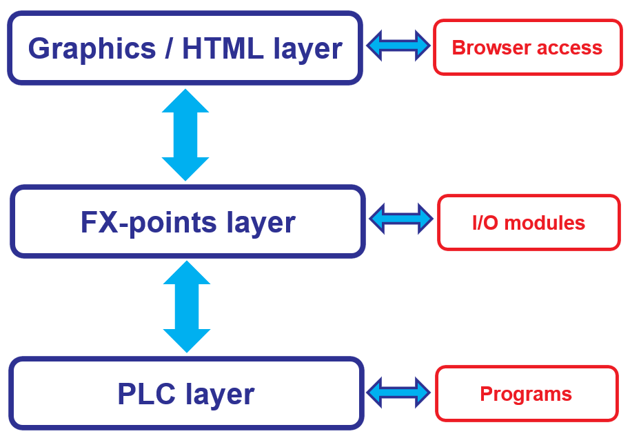
The FX works in three very distinct yet interconnected layers:
Each layer can only communicate directly with the next layer. The passing of information, and especially directing the information and commands, happens through point IDs. We call these point IDs “FX-point IDs”.
Every point - physical and fictive - has a unique point ID which may be up to 29 characters long. This ID is frequently used when the value of a point is needed, e.g.
A point may refer to another point (e.g. DO point is (de)activated based on a time schedule)
IEC programs are referring to FX-points by point ID
Third party software may refer to FX-points through an OPC server
The web graphics are displaying point values using FX-point IDs
This means that in your HTML pages, you will use these FX-point IDs to show the correct value, in the FX-point programming, you will attribute a physical I/O point to the FX-point ID, and in the PLC programming layer, you will set special conditions or do complicated calculations with the value retrieved from the I/O.
This means that the FX-point ID is the most important identifier, because from your graphics or PLC program, you can only connect to an I/O through the FX-point ID, so choose them wisely when you start!
Graphical layer / HTML#
Using the Graphics Editor in the FX-Editor suite, create html pages that can be loaded to your FX-controller.
Alternatively, the Fidelix Graphics / HTML Editor can be used, but there is no integration with the Point-programming or PLC layer, so this is not recommended as it is much more prone to typing errors. The reference manual for this editor however, gives more detailed instructions on how to create or edit graphics and how to add special values (limit values, time values etc.).
It is important to know that you can define a “User level” for each point and each page that you add to the graphics. This means that you can show or hide certain values or pages for different types of users (view only, maintenance, admin, etc.). Read more about User Level in the User Level section.
It is also in the HTML pages where you can define if a value is editable from the UI or not.
Lastly, you can add “buttons” that behave just like physical buttons in the graphics.
For most projects, you will start by creating HTML pages, embedding and choosing immediately the FX-point IDs that will be used throughout the whole project.
FX-Point layer / Point Database#
FX-point IDs are generally chosen when making the graphics, and are subsequently read into the FX-Editor point database where you can parametrise them and connect them to physical I/O’s, or keep them as virtual FX-points. One FX can store up to 2000 (virtual and physical) FX-points. This number includes time schedules, conversion tables, alarm points, set points, etc.
Any manipulation you do inside FX-Editor will be replicated on the FX-controller, meaning that in theory you could do all the FX-point programming on the web interface of the controller. Obviously this is not recommended. Instead, use FX-Editor to parametrise everything and upload from your PC to the FX-controller.
The programming you can do in the FX-points layer are for example; parametrise the PID loop of a set point, set alarm limit values, set digital point on and/or off delays, parametrise a time schedule, link a time schedule to a digital point, group alarms, attribute actions to alarm groups, select the right conversion table to be used for your measurement point, adjust conversion tables, link physical I/O’s to FX-points, and many more things.
NOTE: each measurement point has 8 sub-values, or limit values. They are generally used to store alarm limits related to the measurement point (e.g. supply air lower limit, supply air upper limit, return water lower limit, …)
Each FX-point, whether physical or virtual, can have 3 different so called LockStates. The LockState of a point tells you what process is operating a point. The LockStates are hierarchically organised, meaning that the bigger LockState value will ALWAYS take priority on the lower LockState value. This also means that once a point has been operated on to get it in LockState 1, the value will stay there until OR a different process sets the LockState to 2, OR the LockState is (manually) set back to zero (in reality, more LockStates than 0, 1, and 2 are possible, but let’s get to that later).
LockState 0 or AUTO: This means the point is in its default state. If it is a measurement point, the point value will be simply directly the value the module is measuring, if it is a time schedule, the point will have the direct same value as how the time schedule is parametrised, etc. Basically; things are working in an automatic way.
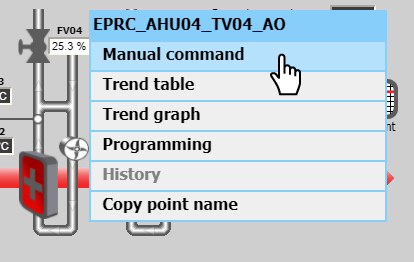
LockState 1 or PROGRAM: This means the program that you wrote in ST-Edit or OpenPCS is the last process to control the point. Note that this LockState will remain active until you actively change the LockState of the point, even if you changed your program and are no longer controlling the point. In this case, you should “release” the point by switching back to AUTO mode in the UI: Note that this LockState will remain active until you actively change the LockState of the point, even if you changed your program and are no longer controlling the point. In this case, you should “release” the point by switching back to AUTO mode in the UI:
Click on your point, choose “Manual command” and click “Auto” to set the point back to LockState 0.
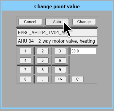
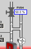
LockState 2 or MANUAL:
This means the value was set from the UI. This is indicated by a blue border around the value as shown on the image. As this is the LockState with the highest authority, any value that would come from the IEC program or from the automatic parametrising of the point are ignored. You can enter a value manually by clicking a point and simply entering a value. It will by default pass into manual mode.
The manual LockState can be released either from the UI by passing to AUTO again as described above, or by overwriting a manual value from the IEC program. This means that even though MANUAL is the highest LockState, you can still grab control from your software, for instance to avoid faulty or extreme values to be entered by unknowing maintenance personnel.
See the description of the functions SetDigitalPointF and SetAnalogPointF in the FX programming reference manual for more details on how to overwrite LockStates.
NOTE: In addition to this, alarm points have three more LockState values to indicate whether the alarm has been acknowledged or not.
In some cases, you will not restart a process until the alarm has been acknowledged, to make sure some (manual or even on-site) action has been taken. More details in the Alarms section.
Different LockState values are also used to change the on or off delay of alarms and other digital points. More details the full Fidelix programming reference manual.
PLC layer#
FX-controllers are programmed following the industrial automation standard IEC 61131-3. We use the program called OpenPCS (issued by infoteam). This is a completely separate program, for which Fidelix provides the correct drivers to program the FX-controller. As mentioned above, OpenPCS communicates solely through the means of FX-point IDs. In principle, the program doesn’t (need to) know if the FX-point is a physical point, or even (to some level) what type of point it is. This separation allows for a very portable architecture, where changes in the hardware (e.g. changing the type of sensor connected, or connecting to a different module) only need to be reflected by minor changes in the FX-point layer parametrising (e.g. simply selecting another conversion table or module).
NOTE: IEC code, IEC program, PLC code, PLC program, OpenPCS code, OpenPCS program, IEC project, … are all terms that are used randomly, but are 100% interchangeable. They basically mean the same thing: the line coding program you write!
Fx-Editor offers an integrated environment with connections to the FX-point names.
While you thus will need OpenPCS for driver support and the compiler, the software simply needs to be installed on your computer, but you will use FX-Editor to write and edit special programs.