FX-3000-C#
Purpose
In this lesson we are learning the main features of the FX-3000-C.
FX-3000-C Freely programmable BMS controller (PLC)#
Controller’s physical components#
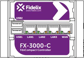
Network ports’ LEDs:
The orange LEDs indicate network activity for each port.
the green LED of LAN1 indicates write operations to the memory stick connected to USB1.
The **green* LED of LAN3 is the controller’s ”heart beat”; slow blinking with 2 second intervals indicates normal CPU operation.
The green LED of LAN2 is briefly lit when the power supply is switched on.
USBs:
The controller has 2 USB ports. With the Update Tool software, the USB1 port can be used to update, consult or reset certain settings that require local intervention. The USB2 port is allocated to the internal router.
Battery:
The internal real time clock is powered by a replaceble CR2016 battery when the controller’s power supply is not connected. It is located behind the lower little door at the front side of the controller.
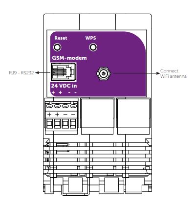
Power supply:
Power (24 VDC) can be provided either from the side (next to the Wi-Fi antenna), or from the bottom, through the click-on connector on the DIN rail. With this connector, FdxCompact modules can be connected to the same power supply. The controller can handle a load of maximum 7A.
Reset button:
Pressing the reset button will trigger a saving of the point data and subsequently restart the controller.
GSM-modem:
The RJ9 port next to the Wi-Fi antenna offers an RS232 interface to the COM1 port of the controller. This is used to send out alarms as SMS messages via an serial modem
Wi-Fi:
The wireless network is hosted by a chip with 1T1R at 2.4GHz and offers a 150 Mbps connection via 802.11b/g/n modes. There is a WPS button on the side of the controller next to the antenna to connect devices without the use of passwords. The default IP address of the controller on the Wi-Fi network is 192.168.12.1.
Serial extension sticker By removing the sticker on the side to access the connection port for the FX-RS485-C module. This module hosts 2 more RS485 ports that can be directly connected to the controller (COM4 and COM5).

Power supply (24 VDC) & Port 3 serial communication (Modbus RTU over RS485)
Verify your skills:#
Recap:#
Check the datasheet to recap the major features: Datasheet
To train more, you can dig in to manual: Programming manual